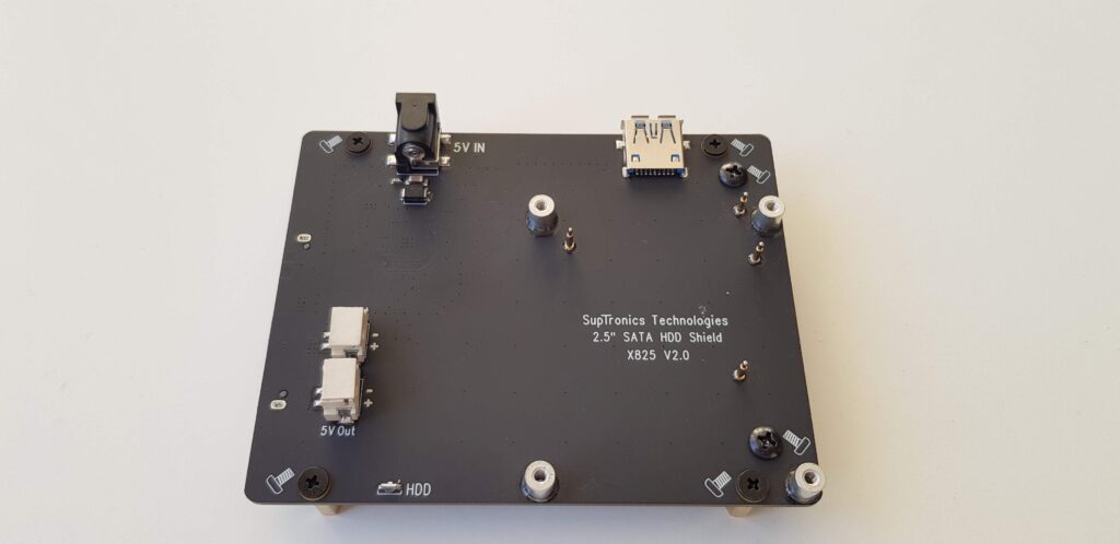
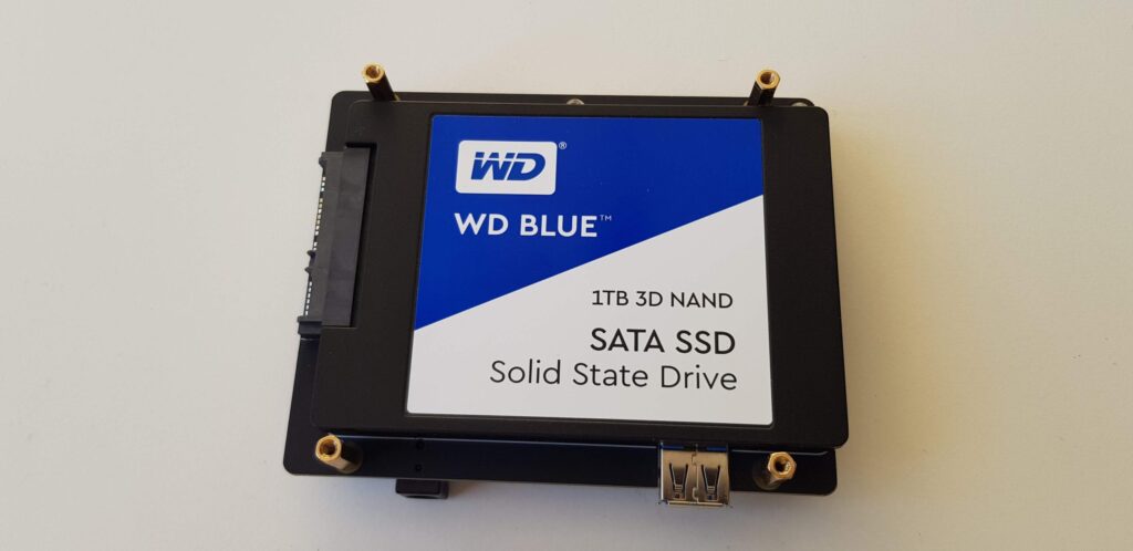
The first thing I put together was the SSD and the SSD shield. It was a bit difficult to get one of the screws to attach to the SSD. The reason was that one of the brackets on the SSD shield was slightly angled in the wrong direction.
After trying 2-3 times without succeeding in attaching the SSD, the anxiety about having to send the product back began to emerge. But with a bit harder force I finally succeeded 🙂
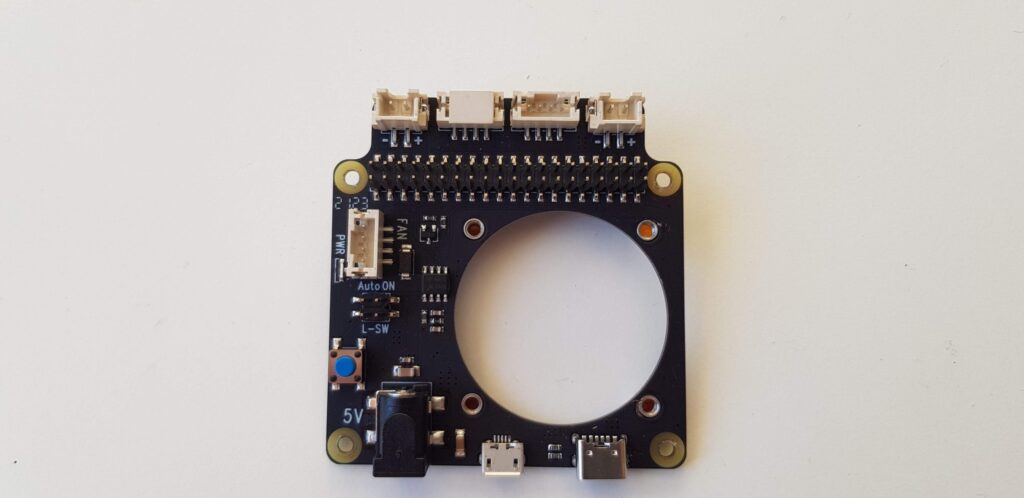
I removed the original fan on the X735 circuit board and replaced it with a Noctua fan instead. Noctua is not quieter but it can get more air through and I think it will last longer than the original fan. Maybe I should have left the original fan on until it broke and then replaced it. But I was too eager 🙂
I had no JST-PH 4-pole female connectors so the solution was to cut it off from the original fan and solder it on the Noctua fan. Not so graceful but it works.
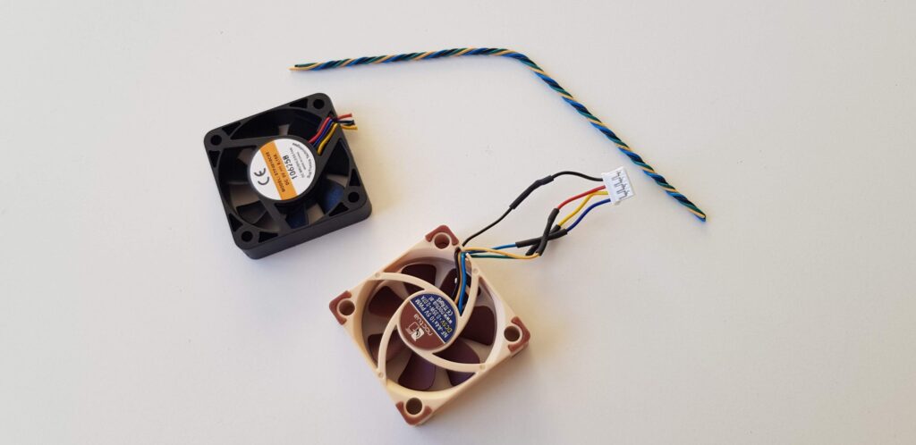
This is the color coding for how I connected the wires:
Pin Type
PWM signal (+5v)
RPM speed signal
+5v
Ground (GND)
Noctua fan cable color
Blue
Green
Yellow
Black
GeekWorm fan cable color
Blue
Yellow
Red
Black
Now to the next problem…
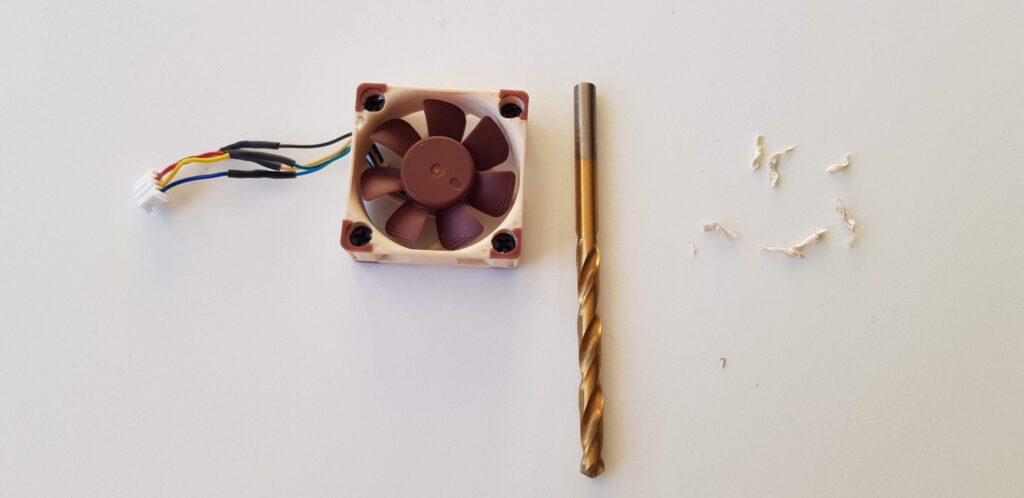
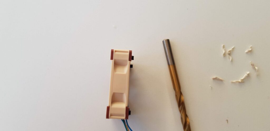
The screws do not reach down to the circuit board to secure the fan. I solved this by drilling 2mm down into each screw bracket with a 5.5mm drill.
Then the screw came through just right.
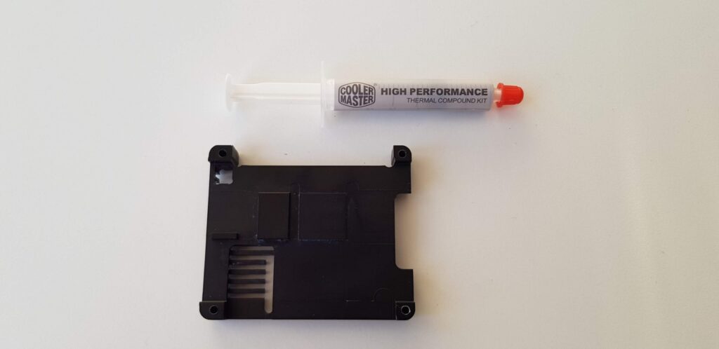
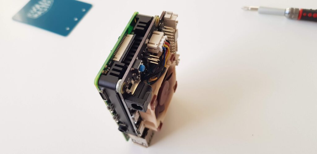
Then it was time for the heat sink. This heat sink is not really intended for this build but I was hoping it would work anyway.
According to my calculations, it would fit under the GeekWorm X735 V2.5 Board. Just put on some cooling paste and put it in place.
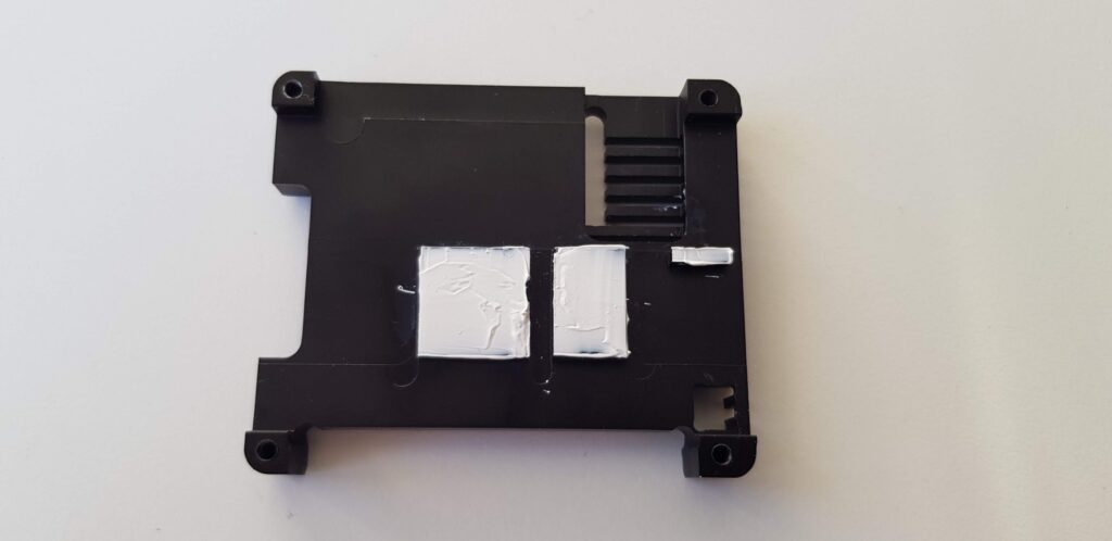
But when I was screwed the X735 board on to the Raspberry Pi, the circuit board bended and touched the heat sink. I was worried that this could lead to a short circuit.
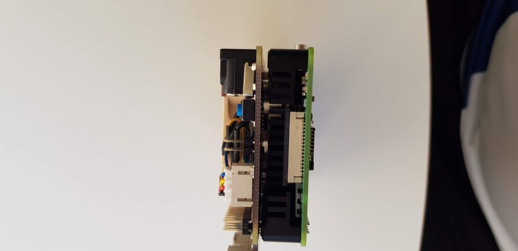
I found some tiles and when I used two of them together it worked perfectly to get the right distance.
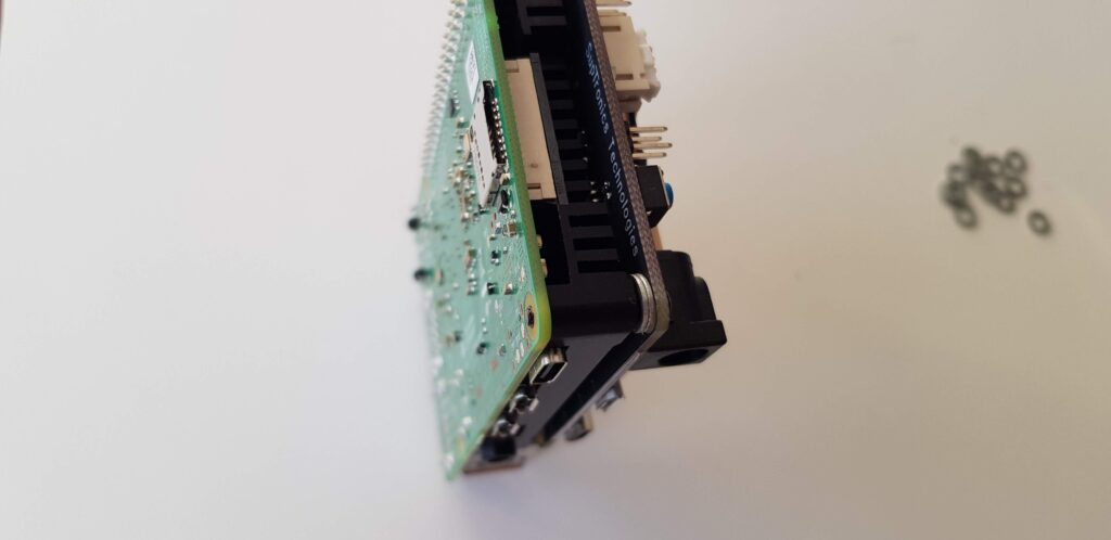
Now the production stooped because the screws that came with the build was not supposed to be used with this type of heat sink, they were too short. I could not use standoffs because of the heat sink. The X735 got attached to the heat sink but did not reach down to the bracket below on the X825 board.
Searched like a maniac but could not find any screws that fit. They where M2.5 17mm and I needed them to be 20mm in length. Searched through all the local stores where I live but not one of them had this little tiny screw. I ended up ordering from Amazon.se. Bought a screw kit that had M2.5 20mm black screws. 300pcs Hex Socket, M2.5 * 3-20mm
I just had to wait for delivery.
Hi there! This is kind of off topic but I need some help from an established blog. Is it very hard to set up your own blog? I’m not very techincal but I can figure things out pretty fast. I’m thinking about setting up my own but I’m not sure where to start. Do you have any tips or suggestions? Many thanks
Hi
I did a Google search and found this https://themeisle.com/blog/how-to-create-a-blog/
It is almost exactly what I did 🙂
My web host has a one-click-installer for wordpress. I only had to click i and add admin and password. Done!
My suggestion is to find a web host that can do the same for you.
Hope that was helpful.
Hello! I’m at work browsing your blog from my new iphone 4! Just wanted to say I love reading through your blog and look forward to all your posts! Keep up the excellent work!